Sunday, November 10, 2019

Helm and console integration part 3 : gelcoat, starboard and leaning post

With the console unit affixed to the top of the existing helm base and with basic coosa integration and fairing complete it was time to take the next iterative steps of gel coating, finding defects, fairing, sanding and repeating.  When a fiberglass part is made in a mold it pops out all shiny and beautiful.  But when gel coating a fabricated work like this, the gel coat goes on with plenty of orange peel which must be sanded flat and then polished using successively finer grit sandpaper (#100, #220, #320, #440, #600, #800, #1200, polishing compound, finishing compound and then finishing wax) in order to obtain that high gloss low porosity shine.  That shine is more important than just for its good looks.  It also makes cleaning the boat easy.  If you leave gel coat with orange peel the dirt collects in the valleys and it is near impossible to clean once the dust settles in.  But after you shine and wax it, the dust rinses off easily.


If you recall how the original strut was put in place for strength you will appreciate how additional layers of glass cloth were added over the top of the strut in the back of the unit and curved nicely to conform to the lines of the boat.


But with each coat of gel coat, all the defects pop out at you so you can go knock them down with 3M vinylester lightweight fairing compound, sand, and then roll on more gel coat.


Eventually it starts looking pretty good.  Here we took a break from the grind to install the helm pump, the starboard drawers and the custom starboard pull out door.   Even though the gel coat isn't polished yet you can see the plan coming together.  Albeit slightly different than our original concept I think it will be just as useful and maybe more so by allowing a 2nd person to operate the fish finder while the driver drives the boat.


Next we made a front plate that we could install the glass helm equipment into.  This plate is removable so that we can get to the wires in back of the equipment if needed.  So the first step was to create a template, and use it to create the front panel out of 3/4" starboard.  We originally wanted to use 1/2" material but it was too thin for the router bits that we had so we went with 3/4" instead.


Since starboard is soft, you have to be very careful putting screws into it or you will mush the screw head into the plastic and deform it.  In order to minimize this, we did a couple things.  First, instead of trying to screw this starboard plate directly into the fiberglass console unit, we drilled holes around the perimeter and installed stainless steel threaded rivnut style inserts.  The trick with these is to just be gentle when using the installation tool.  Instead of collapsing the back of the nutsert the full amount, the goal was to only bulge it out (tried to depict this 2nd picture from the left) a bit so that it would bite into the fiberglass console.  And then of course these 10-24 rivnuts were sealed with 5200.  Use of machine screws instead of wood or sheet metal screws makes it very easy to get just the right tension while not over driving the screw.


As another protection against the screw head embedding into the starboard too far, we used a forstner bit to cut flat bottom divots around the perimeter of the starboard and then used 5200 to install the vee style washer shown at the far right above.  In this way, the force of the screw is spread out more and it make it easier to safely screw the entire back plate into place.  In the picture below notice that we had also mounted the control head for the Glendinning electronic throttle and transmission controls as well as custom made starboard doors for the slanted portion of the console. 


After that we cut out holes and then installed the Garmin 8612, the 7" Argonaut marine touch display, the control head for the new Raymarine EVO-1 autopilot system and the 21.5" custom made touch screen LCD monitor.  You can see that the handset microphone for the Garmin VHF 315 black box radio has been installed and the mic clip is attached to the swing open starboard door that protects the floscan fuel flow meters and two other 7" Argonaut touch screen displays.  In this entire solution there is only one physical switch, and that is for the horn because it is a safety item.  All other switches, including starting and stopping the engines, are done using relays and are controlled by my custom software running on an embedded, fanless PC.  One of these is in the Saloon and one is under the flybridge cowl.  When using Ethernet based relays there is no limit to the number of control points you can install, and everything works independently of everything else.  Relay controlled boats are the way of the future IMO, just like commercial aircraft and many high end cars (like Tesla) do today.


Before we got everything too pretty up there we decided to vector off and install the flybridge helm leaning post.  Here is the unit we purchased, a Fishmaster Pro unit made of large diameter powder coated aluminum tubing.  This unit will be simple and comfortable for sitting or leaning.  It will hold a cooler securely in place in the flybridge and it should be easy to maintain by throwing a leaning post cover over the top of it.  This is the one we bought for that purpose.


As for mounting this leaning post, the flybridge sole does not have any wood in it.  It is a sandwich of fiberglass over something that was called Syncore which is a hard and lightweight but porous material.  It kind of reminds me of a lightweight cement board.  Chris Craft used this instead of balsa so that they would never suffer from rotten deck coring.  In any case, I knew we could not screw into it and expect the screws to hold.

The other usual choice was to through-bolt it but that would require us to take down the headliner inside the boat.  While we will probably have to do anyway that someday, we did not want to add to our workload needed to get out of Virginia by early April.  Besides, if you through-bolt something it will eventually leak.

So the mechanism used to provide bullet proof mounting for this leaning post was to create pads and to glass them in place after having removed the top layer of the flybridge sole and then chipping out the Syncore.  The reason we went to all this trouble is that this leaning post already sits rather high. So we didn't want to glass in some wooden bases and then bolt the chair to those.  Also, if we glass something directly to the flybridge sole, we are really just glassing to a 1/8” sheet of fiberglass that is then bonded to Syncore.   I could just see the two of us sitting in that chair and then being thrown back by a wave only to have the top layer of glass that our chair base was bolted to de-laminate from the Syncore, throwing us backward off the flybridge.

Below shows how we cut out the top layer of the flybridge sole where the leaning post feet would sit and chipped out all the Syncore and then glassed some bolts into place facing up which will be used with crown nuts to bolt the chair down.  As you can see from below, that was probably a smart move because when I cut the area out it was not too difficult to get a chisel in between Syncore and glass
and separate them.


This is what it looked like after chipping out the syncore.  Note that the chair will still sit on top of the original deck and the oval feet of the chair will cover the work shown below by about 3/4" all around.


This is what the pads look like.  They position the bolts properly to align with the holes in the feet and then they are glassed right into the deck.  This will never leak, never give way.  Crown nuts will cap these stainless bolts.


Refurbishing the flybridge ladder

Flybridge Topics

Select which topic you would like to check out:

Flybridge helm refit overview

Flybridge deck and cowl   

Building the glass helm console unit   

Flybridge helm and console part 1   

Flybridge helm and console part 2   

Flybridge helm and console part 3   

Adding the RADAR arch   

Flybridge video cameras    

Refurbishing the flybridge ladder

Sunday, June 2, 2019

Flybridge video cameras


The flybridge of Third wave contains three cameras:

1) A 4k Dahua IPC-HDBW5830RP-Z.  This camera is mounted on the RADAR arch facing aft and pointing down to catch all the action going on in the cockpit in UHD 4k resolution.  This camera supports security analytics as well including triggering alarms if virtual "fences" defined by the user within the field of view of the camera are crossed.  This camera also supports the use of an external microphone so that any sound in the cockpit can be recorded.

2) A GoSea 1080P PTZ vehicle camera.  The details of this camera are provided in the video below.


3) a TBD forward looking navigation camera with build in stabilization.  This camera will be attached to the front of the flybridge cowl and will provide the same view to the driver that he will see by looking over the top of the flybridge console.  The main purpose behind this camera is to record what happens day and night, and to provide infrared night vision for the driver of the boat.  In this way, the driver can see what is ahead of the boat without shining the forward flood light and ruining his night vision.  The most likely candidate for this camera is the Samsung / Hanwha Wisenet III series.

Detailed pictures of and videos from each of these cameras will be posted when they become available.

Thursday, May 30, 2019

Refitting the forward toe rail

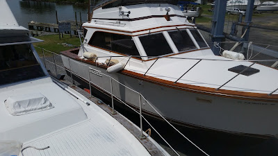
They say a picture is worth 1000 words and so the picture below should tell you why we decided to do a major modernization on the toe rail (which is the wood underneath the lifeline handrail vertical uprights).  In the picture below you can see how the toe rail of our boat stacked up (or fell down as it were) against that of the boat on blocks next to us, a classic Egg Harbor of about the same vintage as Third Wave.  The Egg Harbor has a more desirable welded stainless handrail but we did not want to put our money there.  But the toe rail on the Egg Harbor was freshly varnished at the time whereas ours was worn out grey teak.  The wood was uneven after years of wear and the wood was so old it would no longer take varnish.   And prepping and varnishing the toe rail the proper way, without getting varnish all over everything is no small job.  Yet with the age of our toe rail wood, the best we could hope to expect the varnish to stay was maybe 4-6 months.  Maybe.  Redoing the toe rail twice a year for the rest of our boating lives did not carry much appeal.

Now at this point, a purist would have said it's time to break out the checkbook and buy a new teak toe rail.  A major problem with that, besides all the work involved, is the cost.  I can't quote an exact price but this is thousands of dollars for materials and labor.  As one old timer posting on a boating chat room put it, "Replacing toe rails is not for an amateur. Forming wood to three dimensions is not a skill you duplicate on the first trip. Sorry, this really is not easy.".  And those who do boat repair know damned well.  They figure if you are dumb enough to ask the cost you might be dumb enough to overpay for the work. And of course teak wood is astronomically priced.

Additionally, just putting new teak down doesn't mean you have no maintenance going forward.  Maintenance is simply possible at that point.  A far better option for us was to just rip the rotten teak off and throw it in the dumpster and then glass the seam shut and gel coat the surface.  Then and only then would there be no more varnishing of the exterior bright work.  Yeah I know, a lot of people will hate the idea but none of them offered to re-do the teak every 4-6 months so they don't get a say.  Besides, exterior teak actually makes  boat look old and we would rather have a more modern look that is far cheaper, easier to maintain, and guaranteed not to leak.

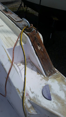
The picture to the left shows more of the "before condition" of the teak toe rail.  We knew that the toe rail covered seams and that there would be a significant amount of glassing, filling and fairing to get it right, but the end result was deemed to be worth it.


Step 1 was to remove all the stainless hardware.  That included the ancient looking and weather worn chrome plated air scoops as well as the lifeline vertical uprights and the old 6" cleats and deck fills. 


The cleats were old, incorrectly positioned, and too small.  Plus there were old style and made of chrome plated brass.  316 stainless is cheaper to buy new for a larger 10" cleat with modern styling and very low maintenance.  Also, the existing cleats had no backing plates.  We fixed all of that by creating 3/8" backing plates from 304 stainless and then drilling and tapping holes.


The old deck fills and hardware all came off without too much resistance.


We tore the old teak wood off easily into small chunks with claw hammers which is a testament to how old and washed out it was.  New teak would have fought us tooth and nail to remove by force.  The remaining brass screws either unscrewed with a Phillips screwdriver or came out with vice grips.


The center of the seam was then ground out with a big Makita grinder polisher equipped with 36 grit flap discs.  Man did this throw some nasty fiberglass dust into the air for 30+ feet all around the boat when it was happening.


We then glassed the seam in with multiple layers of 17 oz cloth and epoxy resin.


And then came the multiple layers of fairing compound.  Spread it on, sand it off, gel coat it in order to see how bad it still was, sand out most of the gel coat and reapply fairing compound.  It took about 4 full cycles of this to get it to a passable state.


The down sloping portions here needed significant glassing and fairing to get them into shape.  There are no shortcuts here.  Any shortcut you take results in an amateurish looking finished product.


Here's the port side.


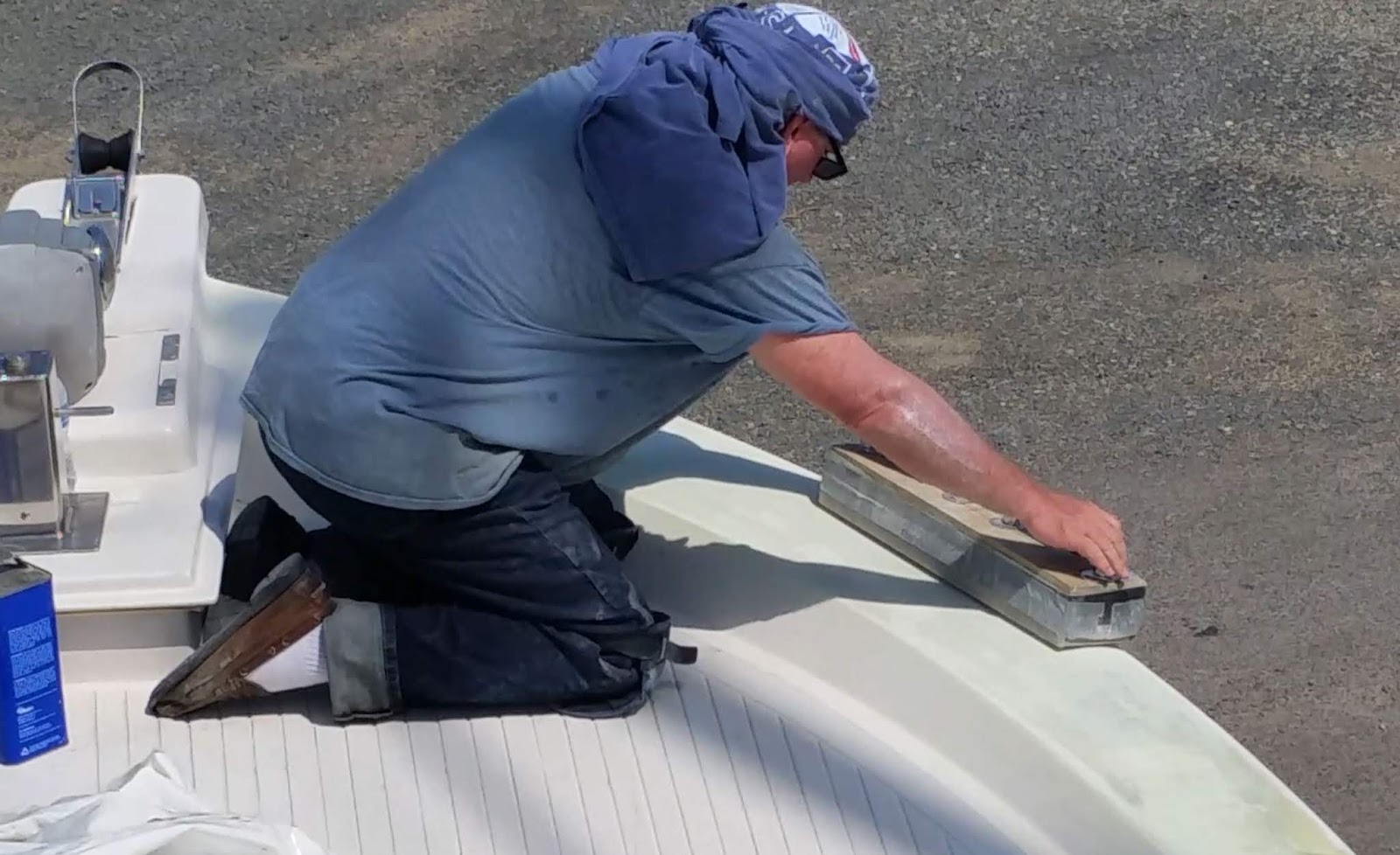
You really can't tell what you have until you put some gel coat on it.  While getting close, this still had too much ripple in it and we had to hit it again with the "long board" which was a piece of 4x6" lumber with handles that sandpaper had been taped to the bottom of.  Once the gel coat was sanded down, another lay of totalboat epoxy filler was added.


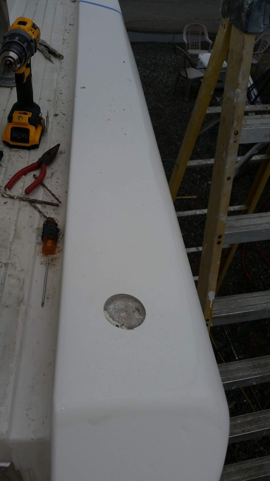
Finally we got the toe rails fair and right all around and so we decided to polish, buff and wax a 6' section just to get a feel for how it would eventually look.  It's hard to tell from the picture but that is literally a show room finish.  The hole is there for the flush mount gas fill deck fitting.


More to come!

Wednesday, May 29, 2019

Blower vent removal

I am not a fan of holes in the side of a boat which are not part of a closed system.  If water goes up a closed system like the generator exhaust, air conditioner water raw water outlet or even in a worst case, the gas vent, at least it doesn't go into the bilge.  In the case of our boat, someone had cut a big fat ugly hole in the side of the boat only about 24" above the water line and then connected an old rectangular bilge blower to the hole.  The blower unit was corroded badly but it still ran.  Still, we would find another way to vent the bilge during engine start that didn't require there to be a big ugly 6" by 4" hole that was covered by a cheap looking louvered plate.


As with the holes in the bottom of the boat, this hole was scarfed although not nearly 12:1.  But it's really not taking any load so I am sure that the contact area will be enough to hold, especially with the use of West Systems epoxy.


Due to the size of this hole, before we patched the front of it we pulled a piece of epoxy soaked cloth across the backside and let it cure.  This gave the patch something to push against when laid in place from the outside.


A layered, tapered patch was created, same as it was for the holes in the bottom, and the hole was gooped up with epoxy resin.


The patch was then squeegeed into place using waxed paper to protect the top layer of the patch from being moved around relative to underlying layers by the squeegee.  We made sure that the ridge in the middle of the hole was filled without voids. 


When we placed this patch, the outside temperature was at the low end of the allowable range.  Thus it took all night to cure to any degree.  As we checked on it over the next couple hours we noted it was slowly sliding down the side of the boat under its own weight.  In order to lock it into place, we taped a masonry trowel which had a lot of surface area on top of it and let it set overnight.


We were lucky that the patch was not fully cured the next morning or we might have had to grind that trowel off of there.  But with some effort we coaxed the trowel free without hurting the patch.


The patch was later sanded and faired and is now ready for gel coating.


Some might be curious where the bilge blower vents were relocated.  We decided to go with twin inline blowers that connect to these stainless louvers, one port and one starboard, that would probably be mistaken for courtesy lights at first glance.  They are up out of the way and all fumes are still discharged outside of the cockpit.  The are up high and safe from water intrusion and have been through many strong storms in the marina already without blowing any water back down into the bilge.  This spot almost looks like it was made for the blower vents.


Click here to see how we handled the rotten toe rail.