With the console unit affixed to the top of the existing helm base and with basic coosa integration and fairing complete it was time to take the next iterative steps of gel coating, finding defects, fairing, sanding and repeating. When a fiberglass part is made in a mold it pops out all shiny and beautiful. But when gel coating a fabricated work like this, the gel coat goes on with plenty of orange peel which must be sanded flat and then polished using successively finer grit sandpaper (#100, #220, #320, #440, #600, #800, #1200, polishing compound, finishing compound and then finishing wax) in order to obtain that high gloss low porosity shine. That shine is more important than just for its good looks. It also makes cleaning the boat easy. If you leave gel coat with orange peel the dirt collects in the valleys and it is near impossible to clean once the dust settles in. But after you shine and wax it, the dust rinses off easily.

If you recall how the original strut was put in place for strength you will appreciate how additional layers of glass cloth were added over the top of the strut in the back of the unit and curved nicely to conform to the lines of the boat.
But with each coat of gel coat, all the defects pop out at you so you can go knock them down with 3M vinylester lightweight fairing compound, sand, and then roll on more gel coat.
Eventually it starts looking pretty good. Here we took a break from the grind to install the helm pump, the starboard drawers and the custom starboard pull out door. Even though the gel coat isn't polished yet you can see the plan coming together. Albeit slightly different than our original concept I think it will be just as useful and maybe more so by allowing a 2nd person to operate the fish finder while the driver drives the boat.

Next we made a front plate that we could install the glass helm equipment into. This plate is removable so that we can get to the wires in back of the equipment if needed. So the first step was to create a template, and use it to create the front panel out of 3/4" starboard. We originally wanted to use 1/2" material but it was too thin for the router bits that we had so we went with 3/4" instead.

Since starboard is soft, you have to be very careful putting screws into it or you will mush the screw head into the plastic and deform it. In order to minimize this, we did a couple things. First, instead of trying to screw this starboard plate directly into the fiberglass console unit, we drilled holes around the perimeter and installed stainless steel threaded rivnut style inserts. The trick with these is to just be gentle when using the installation tool. Instead of collapsing the back of the nutsert the full amount, the goal was to only bulge it out (tried to depict this 2nd picture from the left) a bit so that it would bite into the fiberglass console. And then of course these 10-24 rivnuts were sealed with 5200. Use of machine screws instead of wood or sheet metal screws makes it very easy to get just the right tension while not over driving the screw.
As another protection against the screw head embedding into the starboard too far, we used a forstner bit to cut flat bottom divots around the perimeter of the starboard and then used 5200 to install the vee style washer shown at the far right above. In this way, the force of the screw is spread out more and it make it easier to safely screw the entire back plate into place. In the picture below notice that we had also mounted the control head for the Glendinning electronic throttle and transmission controls as well as custom made starboard doors for the slanted portion of the console.

After that we cut out holes and then installed the Garmin 8612, the 7" Argonaut marine touch display, the control head for the new Raymarine EVO-1 autopilot system and the 21.5" custom made touch screen LCD monitor. You can see that the handset microphone for the Garmin VHF 315 black box radio has been installed and the mic clip is attached to the swing open starboard door that protects the floscan fuel flow meters and two other 7" Argonaut touch screen displays. In this entire solution there is only one physical switch, and that is for the horn because it is a safety item. All other switches, including starting and stopping the engines, are done using relays and are controlled by my custom software running on an embedded, fanless PC. One of these is in the Saloon and one is under the flybridge cowl. When using Ethernet based relays there is no limit to the number of control points you can install, and everything works independently of everything else. Relay controlled boats are the way of the future IMO, just like commercial aircraft and many high end cars (like Tesla) do today.
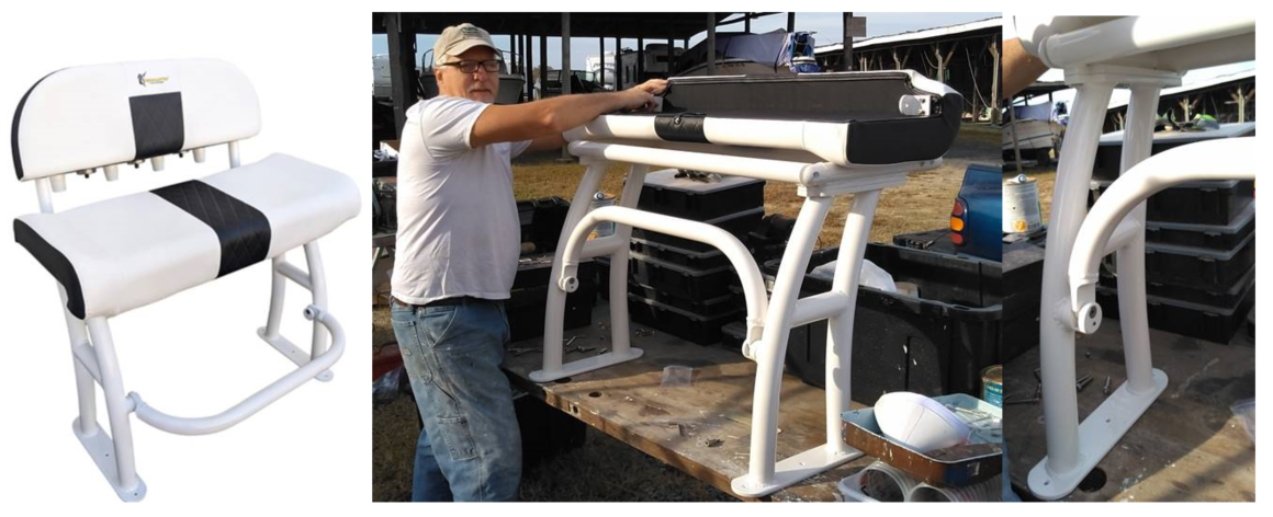
Before we got everything too pretty up there we decided to vector off
and install the flybridge helm leaning post. Here is the unit we
purchased, a Fishmaster Pro unit made of large diameter powder coated
aluminum tubing. This unit will be simple and comfortable for sitting
or leaning. It will hold a cooler securely in place in the flybridge
and it should be easy to maintain by throwing a leaning post cover over
the top of it.
This is the one we bought for that purpose.
As for mounting this leaning post, the flybridge sole does not have any wood in it. It is a sandwich of fiberglass over something that was called Syncore which is a hard and lightweight but porous material. It kind of reminds me of a lightweight cement board. Chris Craft used this instead of balsa so that they would never suffer from rotten deck coring. In any case, I knew we could not screw into it and expect the screws to hold.
The other usual choice was to through-bolt it but that would require us to take down the headliner inside the boat. While we will probably have to do anyway that someday, we did not want to add to our workload needed to get out of Virginia by early April. Besides, if you through-bolt something it will eventually leak.
So the mechanism used to provide bullet proof mounting for this leaning post was to create pads and to glass them in place after having removed the top layer of the flybridge sole and then chipping out the Syncore. The reason we went to all this trouble is that this leaning post already sits rather high. So we didn't want to glass in some wooden bases and then bolt the chair to those. Also, if we glass something directly to the flybridge sole, we are really just glassing to a 1/8” sheet of fiberglass that is then bonded to Syncore. I could just see the two of us sitting in that chair and then being thrown back by a wave only to have the top layer of glass that our chair base was bolted to de-laminate from the Syncore, throwing us backward off the flybridge.
Below shows how we cut out the top layer of the flybridge sole where the leaning post feet would sit and chipped out all the Syncore and then glassed some bolts into place facing up which will be used with crown nuts to bolt the chair down. As you can see from below, that was probably a smart move because when I cut the area out it was not too difficult to get a chisel in between Syncore and glass
and separate them.

This
is what it looked like after chipping out the syncore. Note that the
chair will still sit on top of the original deck and the oval feet of
the chair will cover the work shown below by about 3/4" all around.
This is what the pads look like. They position the bolts properly to
align with the holes in the feet and then they are glassed right into
the deck. This will never leak, never give way. Crown nuts will cap
these stainless bolts.