Sunday, January 24, 2021

Fabricating the cockpit hatch lid

The original hatch was not acceptable for reasons discussed on the Found Condition web page and so we had to figure out what to do. This was very early in the project and so some of the lessons that we learned on this hatch were used, for example on the forward rope locker fabrication.

While we did look on Ebay to see if we could find a hatch of the right size to start with, by the time we began thinking about this hatch we had already decided on making the fish box as big as it could possibly be and still not interfere with existing structure in the bilge such as steering, gas tanks etc.

In hindsight it was probably a mistake to do things in this order because of the amount of time and money we spent fabricating our own hatch door and water channel for the back hatch.  What we should have done was go to a boat salvage yard and find a hatch that was bigger than our needs and then cut the entire hatch and water channel out of the old boat with a chain saw or whatever.  It would have been MUCH easier to integrate this into our deck than it was to create the hatch and water channel from scratch.  For the forward rope locker we learned half that lesson and bought a new hatch lid from Ebay but we still had to fabricate the water channel and that took a lot of time to get it perfect.  There is certainly a chance that we will want to put in more flush cockpit deck compartments in the future and if we ever do that we will definitely start with a hatch door and water channel cut out of another boat.

In any case, to make the hatch we created a simple rectangle of the proper size by nailing some wood strips to an old door that we had put on sawhorses.  We then used bondo to create nice radius' on the corners and then we sprayed it with many coats of PVA (mold release).  

We then tried to spray in some gelcoat but our sprayer died and so we just pushed forward building the hatch and decided to put gel coat on it as a 2nd step.  Most of this will be covered with nonskid anyhow.

 Below is what the top of the piece looked like after popping out of the mold.  We then used hand chisels to cut in the insets for the flush mount hings and hatch pull.


Here is the underside.  That framework on the bottom is just welded 1/8" angle iron in order to ensure it had mechanical strength so that it would not flex or deform under use. Since its completely encapsulated in poly resin it will not rust.


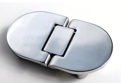
We used high end stainless articulating hinges per below.


Here's a close up of the hinge cut out.  It didn't have to be perfect because gel coat would be making up the difference.


The hatch pull is nothing fancy.  The main requirement for this was that it had to be 316 stainless and flush mount.


Here's the completed hatch door which has been gel coated and is test fitted to the cockpit. Note the splatter treatment on the bottom which adds a very professional inside look.  In order to get this nice blue we had Home Depot sell us an ounce of bright blue paint coloring and we just mixed that into the white gel coat.  Yes they make blue gel coat but this was cheap and fast and good enough for a bilge facing hatch door.


Foredeck Topics

Fabricating the forward locker

Adding the bow custom pulpit and Samson post

Refitting the forward toe rail

Upgrading the forward lifeline


Creating the insulated fish box

The picture below shows the newly created cockpit hatch hole with water channel, the reinforced deck lid to the left, and the newly fabricated fiberglass fish box sitting down in the bilge.  The fish box will eventually drop down onto support "feet" or landing pads which keep the base from moving around while keeping the top of the box flush with the inside of the water channel.

We built the box by making a form for it out of 2x4 lumber and lightweight press board, only a few steps more sturdy than cardboard.  The box is tapered toward the bottom so that we could get it out of the mold easier but we didn't use enough PVA (Poly Vinyl Alcohol) for mold release and we eventually had to grind the press board mold away to get the box out.


When the box is not in place the hatch allows good access to the bilge space under the cockpit sole.


So at this point we had a sturdy fish box but it had no insulation and we decided that we might have to keep ice from melting in it for a long time.   So we then considered how to add insulation after the fact.  We again used the same medical grade glass infused foam material that we had made the cockpit console from.  


We had some pieces that were already nice and thin - 3/4" thick, so we cut those up and glued them to the inside of the box as shown.


After covering the interior walls and bottom with this foam, we glassed in all in place. 


Here's another angle.


We then sanded and faired it before hitting it with an other few heavy coats of gel coat.  Finally, and this is not shown, we added rope handles to the ends to make lifting and carrying easier.


Tuesday, January 5, 2021

Electrical Topics

Electrical distribution

Repairing a burned up shore power connection

Generator installation 1

Generator installation 2

Repairing a burned up shore power receptical

A couple years ago we installed new marine grade (Marinco) shore power inlet connectors, having moved them from the outside of the boat where they were subject to constant salt spray to being just inside the cockpit. They connected to the main electrical panel through 30 amp breakers. Recently my helper, who was staying on the boat during nights as he worked on it during the day without me there, woke up to this scary mess. If you look closely you can see the power is still on to that yellow cable...  The shore power cable was only a few months old.


The wires in back of the unit were covered in soot but undamaged.  So all the heat had clearly been generated in the connection itself, not in the wiring.  The load on the failing circuit at the time was judged to be about 1500 watts (a single electric heater).


As you can see, the center of the connector, including all 3 of the connector tines, are simply gone!  So this was less of a fire per se and more of an arcing situation. The only way for this metal to completely disappear is to have been vaporized via arcing.


We used 10 ga marine approved wire for the connection and if you measure from the connector to the panel and then back to the connector it is no more than 50 feet.  10 ga is the recommended gauge for 30 amps at that distance.  But we know that the problem was in the connector, not in the wire.


Needless to say we bought 2 brand new connectors and then created a custom polished 316 stainless backing plate for enhanced fire protection going forward.


The final result (before refinishing the gel coat) is shown below.  Better, stronger, faster:  We can rebuild it...


Sunday, January 3, 2021

Hull Topics

Adding the dive platform

Replacing existing seacocks and filling deprecated holes

Making a seacock backing block from scratch

Removing through hull blower and filling the hole

Installing through hull seacocks

A lot of people have their own ways of installing seacocks in the hull of a boat.  The previous owner of Third Wave did what many used to do years ago which was to connect the seacocks to through hull fittings as shown below. 


While it was widespread practice at the time, we now know that seacocks and through hulls are the number 1 cause of boats sinking at the dock.  This is not something you just recover from.  The boat must be gutted, all new electronics, all new wiring, all new engines, etc.  It's basically a total loss.  


When something like this is at stake, there is no such thing as "overkill" in an implementation IMO.  This became such an issue that ABYC came up with a standard that says a seacock must withstand 500 lbs of force to the inboard portion of the unit for 30 seconds without water ingress.  This link shows what 500 lbs of lateral force does to this Forespar Marelon seacock.  While the seacock didn't fail, it very likely allowed water to intrude due to deflection.  It was this video that made me decide to come up with my own mechanism for installing seacocks so that they would easily be able to pass ABYC lateral load tests and without any deflection or damage to the unit.

In most cases I used 1/2" G10 pultruded fiberglass, 1/2" thick but in the example shown here, the backing plate material never showed up in time so we laminated a few pre-made 1/4" thick glass and poly sheets together to make the basic backing plate.  Below you see the plate with 3 of the stainless bolts and crown nuts already installed.  This blog post shows the process used to install the the 4th and final nut and bolt.  Here is the top with 1 bolt still needing to be installed.


And here is the bottom.


The position of these nuts is critical, especially when dealing with stainless nuts and bolts like we are doing.  If they are off just a little bit, the stainless will gall and then you will have to cut it out and start over.  So there is no such thing as being "close enough" here.  It must be exact.  And you cannot be exact by eye.  So you cannot just set the seacock on the backing material and then mark the holes like you were doing a wood working project.  The first nut installation is the easiest because it is the base for all the other nut placements but after that you have to follow a process which guarantees mechanical alignment.  That is why there are so many steps below.  The same process is followed for nuts 2, 3 and 4.  Below I will show the sequence just for nut and bolt number 4 (because Perko seacocks have 4 installation holes).

The first step is to find the exact center of the hole you are working on.  Given that this post covers the last hole, the other 3 holes already being done, just bolt the seacock to the backing plate with the 3 nuts and bolts that are already installed.  Then, from the top, take a drill that is the same diameter as the seacock hole and drill in about 1/4".  DO NOT drill all the way through yet!  All you are doing is finding the exact center of the hole right now.


After that's done, that a small drill, like 1/16" and place it in the center of the depression that you just created and then drill straight down through.  Many people cock the drill at an angle without knowing it and if you are prone to do this, use a square to make sure you are straight up and down.


Now flip the plate over and you will see the small hole you just created.


Now you need to find two forstner bits for your drill and this is based on the size of your crown nut.  The first drill is the larger of the two and that creates an inset ledge for the crown nut.  The second creates a void for the body of the nut.


Starting with the larger of the two bits and drilling from the bottom of the plate...


... you create a small disc like cutout for the crown of the nut as shown below.


You know you have gone deep enough when you can hide the crown in the depression as shown below.  It pays to go slow in this process until you have measured like this a few times and get a feeling for it.


Now you use the smaller forstner bit to create a void where the body of the nut will be pressed into.  It is key that you drill just the right depth here.  The easy way to measure this is to hold the crown nut up to the drill bit and see where the top of the nut lands on the drill if the base of the crown is held next to the cutting teeth of the forstner bit.  By the way, Harbor Freight sells a very low cost forstner bit set that has both of the bits I needed to do this job (which uses 3/8-24 crown nuts and 1-1/4" long 3/8-24 stainless bolts).


df


This second bit is then used to cut a concentric void within the first larger diameter cut.


Here is what it looks like when done with the forstner bits:


Now flip the plate back over and install any bolts for which embedded nuts are already present and then go ahead and carefully drill straight down from the top all the way through to the other side.


Once this is done, remove all the existing bolts and then place the crown nut body up into the hole from the bottom and use the nut and a flat washer on top to screw it up into place.  The smaller forstner bit will have drilled a cavity that is a bit too small for the nut but as you wrench it up into position, the corners of the nut will dig into the glass material and displace it so that the nut becomes press fit into the glass.  I found that using fine threat bolts made this process smooth and easy because more turns to do the same work means more force is applied per turn.  It's like using a lower gear and it makes the press fit operation very easy.


Once this is done, all 4 nuts will have been perfectly placed, so perfect that you can screw the seacock down to the plate by hand.  You know that stainless galling is a threat if you have to use any real force at all getting the bolts to cinch down.  It means you have misalignment between the 4 nuts.  If this happens then you are at risk of having to start over.  Note that the use of anti-sieze compound like this is recommended for stainless nuts and bolts, especially where they will be torqued down pretty hard.

The finished backing plate as viewed from its underside is shown below.

The hull is then roughed up in the region of installation with a grinder or a rotary tool with a flapper sanding pad (these work well with my Makita polisher...) and then the base plate is glued to the hull with 5200.  The plate is held fast to the inside of the hull by screwing the straight threaded mushroom intake piece tightly up into the seacock while the seacock is bolted to the base (this step is not shown).  After the 5200 cures, the mushroom pickup is unscrewed and the seacock is unbolted from the base backing block and the 5200 is holding it all in place securely.  

The base block is then glassed securely to the hull as shown below.  When the glass is cured, just bolt the seacock down and reinstall the intake mushroom from below (with sealant of course) and you are good to go.  This is massive overkill for sure but it will be nearly indestructible.  Also, with this setup you can change the seacock out pretty easily even while in the water.  Just have a diver place a larger styrofoam cup over the mushroom intake, and then in 2 minutes you can unbolt the seacock from the bilge side and spin it off the mushroom intake.   Then spin a new seacock back on, bolt it down and you are good to go.